Species-specific depth profiling for in situ 3D imaging – InFeRa
This project aims to develop a new imaging method called InFeRa that combines spatially gated InterFerometric imaging (InFe) with stimulated Raman scattering (Ra). InFeRa will provide label-free, three-dimensional (3D) in situ imaging of chemical and (bio)molecular processes in different materials.
The breakthrough we foresee is the design of a single instrument delivering:
- Simultaneous visualization of embedded structures and formations/deformations in 3D.
- Information of biochemical processes.
- Information on the generation and abundance of specific species.
- Information of structural changes caused by specific species.
A schematic of the optical principle of InFeRa is shown in Fig. 1.
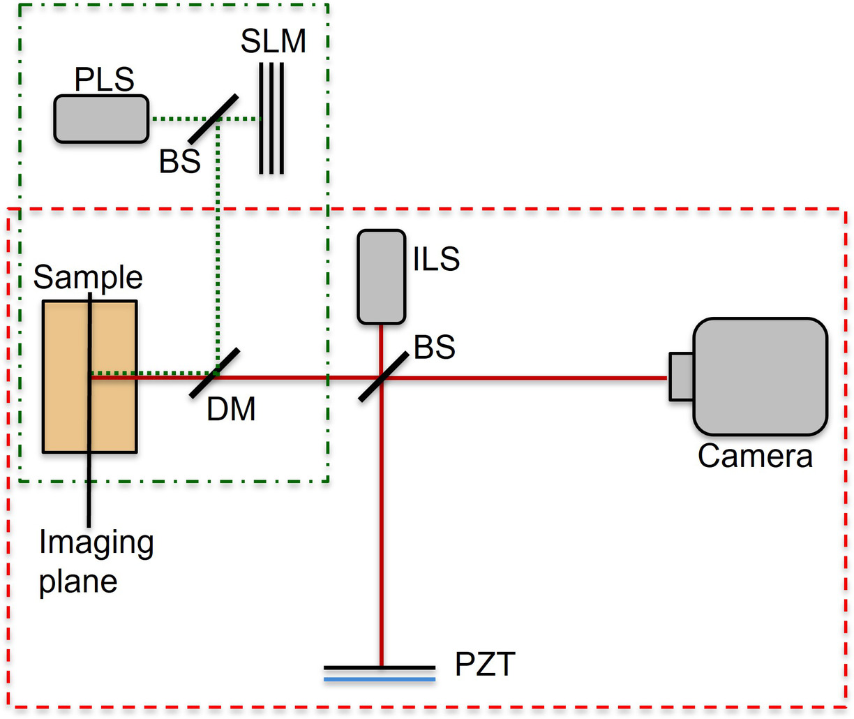
Fig. 1) Sketch of principle for the proposed instrument showing the pump laser source (PLS), beamsplitters (BS), a spatial light modulator (SLM), the imaging light source (ILS), a dichroic mirror (DM), a piezoelectric mirror (PZT) and a camera. The components used for the SRS and interferometric imaging can be seen green dashed dotted square and the red dashed square, respectively.
So far, we have been working on interferometry and SRS separately. The primary results from both parts are presented in the upcoming sections.
Depth-resolved Speckle Correlation
In this part of the project, the close relationship between speckle correlation and depth gating is investigated. The imaging system is based on a phase-stepped imaging Michelson-type interferometer. Fig. 2 shows a photograph of the optical setup, The laser beam from a HeNe laser passes through a rotating diffuser (RGG) to generate a spatially quasi-incoherent beam that is led to a second fixed diffuser (GG). The resulting diffracted beam will be diverging (i.e. the light scatters in a cone shape). By controlling the distance between the diffusors and the aperture size D, the size of the spot hitting the second diffusor and consequently the divergence can be controlled. The sample is placed on a translation stage in one of the arms of the Michaelson interferometer and the optical path distance of the reference arm is adjusted så that it is equal for the two arms. The correlation is then calculated for several small displacements of the reference arm mirror, and the maximum correlation value is reached when the path length in the two arms is equal, providing an image of the sample. The video shows the resulting image from the system as the displacement of the reference arm is increased. The video shows the resulting image as the reference arm displacement is increased. A thorough description and the results can be followed in references [4,5,6].
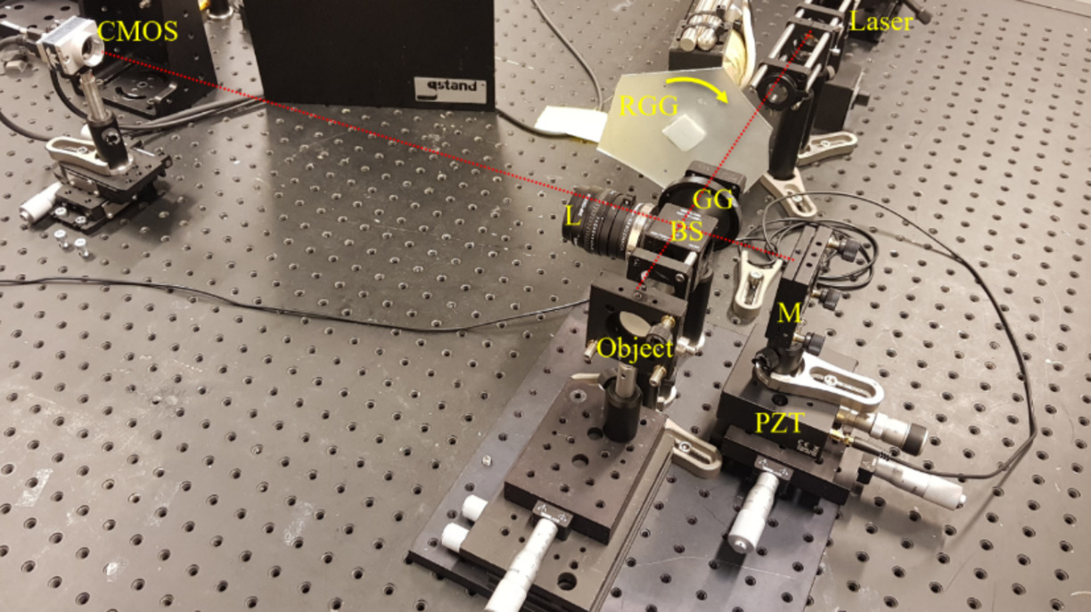
Fig. 2) Photograph of a prototype of coherence-gated interferometry system showing the HeNe laser, rotating diffusor (RGG), fixed diffusor (GG), beamsplitter (BS), mirror (M) on a piezo-electric element (PZT), Object, which is the sample. The object (sample) was imaged with an objective, L, (Component-S 5.6/100, Schneider Kreuznach, Germany, magnification = 6.6) and a digital camera (Genie Nano M2420, Teledyne Dalsa, Canada).
Investigation of the spatial generation and control of stimulated Raman
InFeRa aims to provide 3D information, thus it is important to know where in a sample the SRS signal is generated. SRS is generated in a sample only if two laser beams, whose difference in wavelength matches a Raman line, overlap each other in space, time, and polarization. Thus, the experimental principle was to use one collimated laser to illuminate the sample volume. A second beam was focused into this volume to study where the signal was generated. Experiments and computer simulations were performed using the strong 2934cm-1 Raman line of ethanol.
In our first experiment [7], a spatial light modulator (SLM) was used to control where the SRS was generated in the sample. The spatial position of the generated SRS was controlled by inserting an SLM into the pump beam path, see the left of Fig. 3. The right of Fig. 3 illustrates how the SLM can be used to probe the sample at different locations in the glass cuvette and Fig. 4 shows the results obtained by imaging the SRS signal due to such motion.
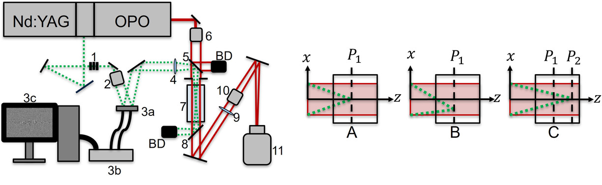
Fig. 3) To the left: A schematic of the optical system. A Q-switched 1064nm Nd:YAG (Continuum PL 8000) was used to produce the two laserbeams. 1) a rotator and 2 thin film polarizers, 2) a 3x Galilean telescope, 3a) SLM head (Hamamatzu X10468-04 LCOS-SLM), 3b) SLM control module, 3c) computer, 4) 250mm lens, 5) beam splitter, 6) 16 times magnification, 7) cuvette containing ethanol, 8) 532nm mirror, 9)250mm lens, 10) a cube containing two edge filters, 11) PCO edge camera with an absorption OD 2.0 filter, an RG 630 filter and BG39 filter. To the right: A Stokes beam, read tinted area, is illuminating a larger area inside the sample, black square. The pump beam, green dotted line, is focused into the sample and the volume that is illuminated with the Stokes light. (A) The pump light is focused on the plane P1 centered at the z axis, (B) the pump light is phase modulated and focused on the plane P1 but not centered on the z axis, (C) the pump light is phase modulated and focused on the plane P2 centered at the z axis.
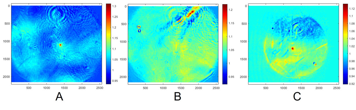
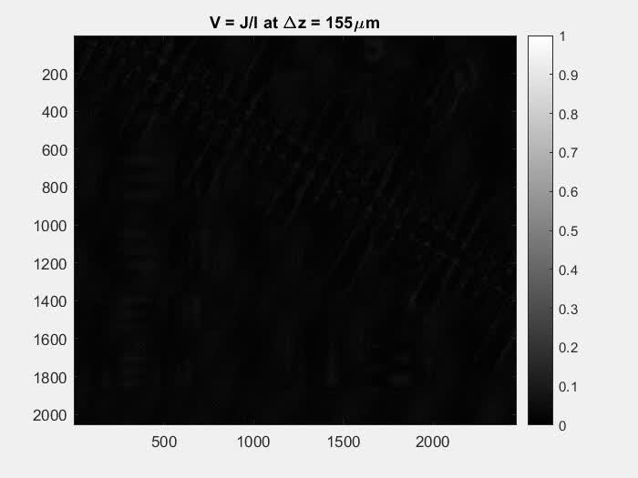
Fig. 4) (A) SRS gain of the Stokes light (red dot) in the focal plane of lens (4). (B) The dot has been moved to a plane closer to lens (4) and no Stokes gain can be seen. Note, the read areas are disturbances from convection and a particle in the sample. (C) The camera position has been adjusted to match the dots plane and the SRS gain can be seen again. In (A), (B) and (C) the x and y axis are the number of pixels in the camera image and the color bar represents the ratio between the signal and reference image. The field of view in (A) and (B) is 10mm×8.4mm and in (C) 14.6mm×12.3mm.
In Fig. 5, the second experimental setup used for the investigation of the SRS generation [8, 9, 10] can be seen. The left image in Fig. 6 shows the crosssection from the computer-simulated SRS generation along the z-axis can be seen. The right image in Fig 6 shows a comparison of the generated SRS light from the experiment and simulations at different propagation lengths through the sample.
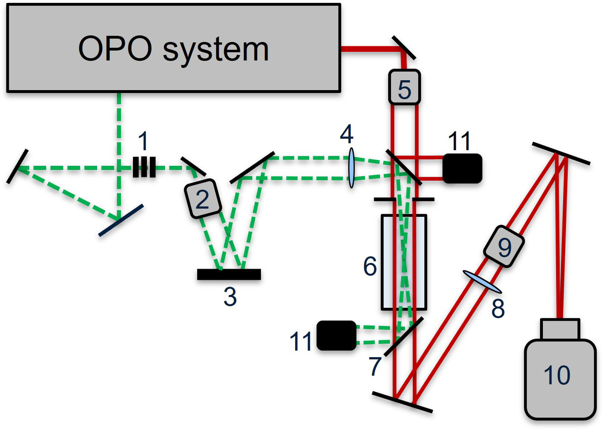
Fig.5) A schematic of the optical system. A Q-switched 1064nm Nd:YAG (Continuum PL 8000) was used to produce both the pump and Stokes beams. 1) a rotator and 2 thin film polarizers, 2) 250mm lens, 3) 16 times magnification, 4) dicroic mirror,5) cuvette containing the sample, 6) 532nm mirror, 7)250mm lens, 8) a cube containing two edge filters, 9) PCO edge camera with an absorption OD 2.0 filter, an RG 630 filter and BG39 filter
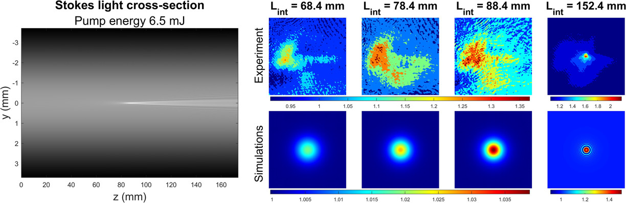
Fig. 6) To the left: a crosssection of the simulated SRS interaction through the sample. The light propagates from the left to the right. The brighter is the generated SRS at the pump beam focus. To the right: the generated SRS (brighter areas) increases as the interaction length increases.
Current and future work
Currently, we are exploring a two-camera speckle correlation imaging system, which enables robust phase gradient imaging as it simultaneously captures a reference and sample image, see Fig. 7. This will speed up the imaging acquisition of InFeRa compared to the initially investigated use of SLM [7]. The next step is to combine the speckle correlation imaging system with SRS.
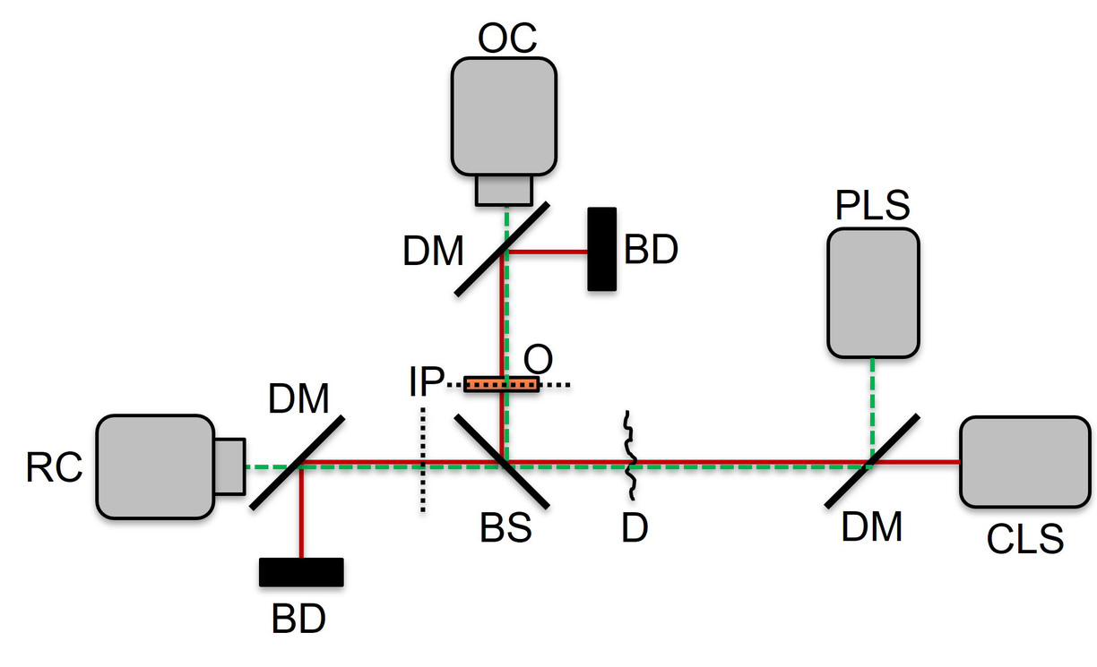
Fig. 7) The alternative imaging system showing a pulsed laser source (PLS), a continuous laser source (CLS), a dichroic mirror (DM), a beam splitter (BS), the imaging planes (IP), the sample (S), beam dumps (BD), the object camera (OC) and the reference camera (RC).
Funding
This project is financially supported by the Swedish Foundation for Strategic Research (ITM17-0056) the Kempe Foundation and LTUs lab fund.
References
- Wahl J, Sjödahl M, Ramser K. Single-Step Preprocessing of Raman Spectra Using Convolutional Neural Networks. Applied Spectroscopy [Internet]. 2020;74(4):427–38. Available from: https://urn.kb.se/resolve?urn=urn:nbn:se:ltu:diva-77138
 External link.
 - Krige A, Ramser K, Sjöblom M, Christakopoulos P, Rova U. A New Approach for Evaluating Electron Transfer Dynamics by Using In Situ Resonance Raman Microscopy and Chronoamperometry in Conjunction with a Dynamic Model. Applied and Environmental Microbiology [Internet]. 2020;86(20). Available from: https://urn.kb.se/resolve?urn=urn:nbn:se:ltu:diva-80312 External link.
- Krige A, Sjöblom M, Ramser K, Christakopoulos P, Rova U. On-line Raman spectroscopic study of cytochromes’ redox state of biofilms in microbial fuel cells. Molecules [Internet]. 2019;24(3). Available from: https://urn.kb.se/resolve?urn=urn:nbn:se:ltu:diva-73003 External link.
- Dembele V, Wahl J, Sjödahl M, Ramser K. Correlation properties of a spatially quasi-incoherent imaging interferometer. Applied Optics [Internet]. 2022;61(19):5806–12. Available from: https://urn.kb.se/resolve?urn=urn:nbn:se:ltu:diva-92225 External link.
- Dembele V, Wahl J, Sjödahl M, Ramser K. Depth-resolved interferometric imaging utilizing a spatially quasi-incoherent light source. In: Proceedings Digital Holography and 3-D Imaging 2022 [Internet]. Optica Publishing Group; 2022. Available from: https://urn.kb.se/resolve?urn=urn:nbn:se:ltu:diva-94793 External link.
- Dembele V, Wahl J, Sjödahl M, Ramser K. Depth-resolved speckle correlation using quasi-incoherent imaging interferometry. In: Proceedings OSA Imaging and Applied Optics Congress 2021 (3D, COSI, DH, ISA, pcAOP) [Internet]. Optical Society of America; 2021. Available from: https://urn.kb.se/resolve?urn=urn:nbn:se:ltu:diva-87551 External link.
- Eriksson R, Gren P, Sjödahl M, Ramser K. 3D Spatial Control of Stimulated Raman Scattering Using a Phase Spatial Light Modulator. In: Proceedings OSA Imaging and Applied Optics Congress 2021 (3D, COSI, DH, ISA, pcAOP) [Internet]. Optical Society of America; 2021. Available from: https://urn.kb.se/resolve?urn=urn:nbn:se:ltu:diva-87595 External link.
- Eriksson R, Gren P, Sjödahl M, Ramser K. 3D spatial control and the spatial generation of stimulated Raman scattering in ethanol [Internet]. ECONOS European Conference on Non-linear Optical Spectroscopy, September 25-28, 2022, Kiruna, Sweden; 2022. Available from: https://urn.kb.se/resolve?urn=urn:nbn:se:ltu:diva-97135 External link.
- Ronja Eriksson, Per Gren, Mikael Sjödahl, Kerstin Ramser Stimulated Raman scattering imaging – 3D spatial generation, ICAVS12, 12th International Conference on Advances in Vibrational Spectroscopy, Krakow, Poland, 2023, https://icavs.org/storage/file/core_files/2023/8/30/5a4b090a392468404c0e8808ce515ba4/ICAVS_Abstrakty_2023.pdf External link.
- Eriksson R, Gren P, Sjödahl M, Ramser K. Investigation of the Spatial Generation of Stimulated Raman Scattering Using Computer Simulation and Experimentation. Applied Spectroscopy [Internet]. 2022;26(11):1307–16. Available from: https://urn.kb.se/resolve?urn=urn:nbn:se:ltu:diva-90344
- https://urn.kb.se/resolve?urn=urn:nbn:se:ltu:diva-87551 External link.
- Kerstin Ramser, (invited speaker) Dr. Joel Wahl, Dr. Fenja Knöpp, Prof. Norbert Weissmann, Dr. Eynas Amer, Prof. Mikael Sjödahl, M. SC. Eng Ronja Eriksson Stimulated Raman scattering and resonance Raman spectroscopy combined with holography, interferometry and video imaging, ICAVS12, 12th International Conference on Advances in Vibrational Spectroscopy, Krakow, Poland, 2023, https://icavs.org/storage/file/core_files/2023/8/30/5a4b090a392468404c0e8808ce515ba4/ICAVS_Abstrakty_2023.pdf External link.
- Eriksson R. Direct imaging of Stimulated Raman scattering : 3D spatial control and spatial generation [Internet] [Licentiate dissertation]. [Luleå]: Luleå University of Technology; 2022. (Licentiate thesis / Luleå University of Technology). Available from: https://urn.kb.se/resolve?urn=urn:nbn:se:ltu:diva-90346 External link.
- Wahl J. Multimodal applications in medical technology that utilize Raman spectroscopy [Internet] [PhD dissertation]. [Luleå]: Luleå University of Technology; 2022. (Doctoral thesis / Luleå University of Technology 1 jan 1997 → …). Available from: https://urn.kb.se/resolve?urn=urn:nbn:se:ltu:diva-87915 External link.
Contact
Kerstin Ramser
Mikael Sjödahl
Updated: