The John Field Laboratory
The Division of Fluid and Experimental Mechanics together with
the Division of Materials and Solid Mechanics have chosen to invest in a joint laboratory for advanced mechanics research.
Background to The John Field Laboratory
A common strategy has resulted in the following objectives to be achieved within two years.
Luleå University of Technology has one of Europe's leading and well-functioning laboratory for advanced measurements of flow and deformation and several concepts for making measurements in the field. We use and are constantly developing new methods for laboratory and field.
We are now working to realize that goal. The area measurement techniques for studies of mechanical phenomena is now developing rapidly. New photonic components makes it possible to measure phenomenon at a resolution and accuracy that previously were not possible while accelerating computer development enables the storage and processing of large amounts of data in short time. This means that we can study the complex processes in intricate shapes, something that was previously impossible. Advances in mechanical field also means that interest in advanced measurements increases. Among other things, in order to validate numerical models, but also to produce data on which calculations do not work at all or to study new phenomena. Advanced measurement technologies will additionally together with on-line simulations increasingly be used for process control.
The name of the John Field Laboratory aimed at LTU's honorary doctor Professor John Field at the Cavendish Laboratories in Cambridge which recurrent have spent a few weeks a year at Luleå University for over thirty years.
Current status
At TVM there is currently a large arsenal of externally funded and self-developed measuring equipment for measuring mechanical phenomena. Examples of equipment are:
- Particle Image Velocimetry
- Micro Particle Image Velocimetry
- Laser Doppler Anemometry
- Laser Doppler Vibrometry
- Image correlation
- Stereoscopic image correlation
- Holographic methods
- Pulsed laser systems
- High-speed cameras
- Thermal camera
- Micro X-ray tomography.
Current departments, mainly the subject Experimental Mechanics, also develop their own unique measurement equipment. The equipment is mainly used for measurements in the laboratory but also in the field and contribute to publishable results and results useful for society and industry. Moreover, they are an important element in our advanced courses. There are also additional equipment on other subjects at the institution such as Machine Elements and Energy Technology. The grouping can therefor be seen as leading in Sweden regarding advanced measurements of flow and deformation. We have also hired a research engineer with the task of coordinating and ensuring the availability of the lab. The aim is to allow for other subjects at the university and externally to station some of their experimental research in this lab.
Investments
Below is a list of equipment we have primarily chosen to invest in the coming year.
- Purchase of Laser Doppler Velocimeter.
- Upgrade of PIV system.
- Upgrade of Micro-PIV system.
- Purchase of two-cavity OPO.
- Upgrade of micro X-ray tomograph.
- Upgrade of Laser Doppler Vibrometer.
- Purchase of high speed camera:
Funding
Funds for this initiative come from LTU's lab fund and the following financiers.
- Kempe
- Vinnova
- VR
Our equipment
To increase the quality and confidence of computer simulations, experiments are essential. Our laboratory has advanced equipment to measure flows, velocities and pressures using different methods.
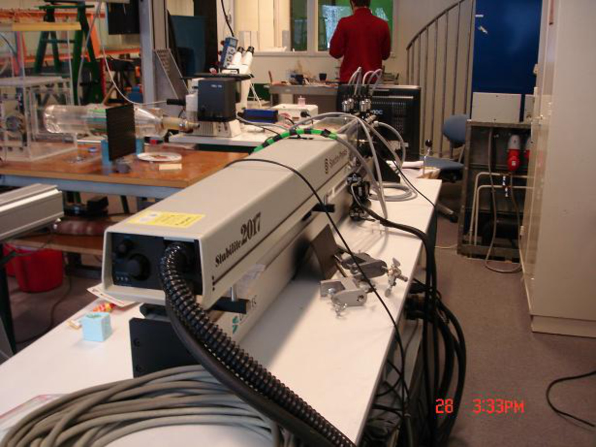
Laser Doppler Velocimetry, also called LDA, provides the ability to measure flow velocities as long as you have visual contact with the flow. This is achieved by creating a moving diffraction pattern originating from laser beams, allowing the use of the Doppler effect to measure particle velocities at a point. In the department we have an LDV system from Dantec.
Particle Imaging Velocimetry (PIV) measures instantaneous information about the entire flow field by comparing snapshots of a seeded flow. A recently purchased PIV system is now used for various research projects at the Fluid Mechanics Laboratory.
Several stationary flow sets in our laboratory are used to exploit measurements with the above equipment.
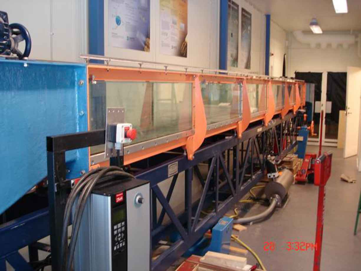
The water tunnel above allows the study of different setups, including single channel flow. Transparent walls allow the use of optical measurement techniques.
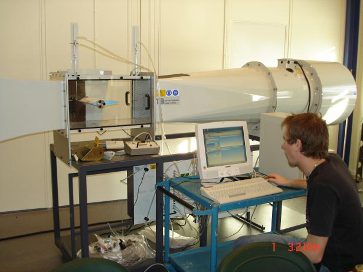
The wind tunnel above is of an open nature and includes a balance to measure air resistance and lift/down force on, for example, model vehicles.
Updated:
Page author: Contact us